MANUFACTURE OF CUP HOLDER FOR PORTABLE MISSION CONTROL UNIT
MANUFACTURING PROCESS
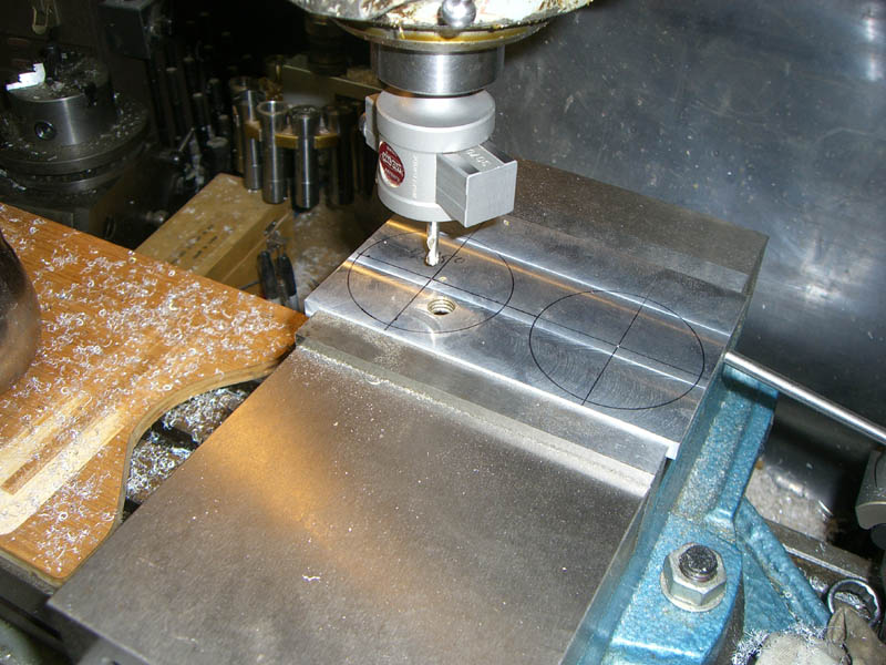
1. Square up a block of 6061 T6 aluminum to 6.00” X 3.00” X .250” on Induma mill.
2. Lay out circles to be cut on 1.50” centers from the front and left edges. Go to Medical Cabinet and select a bandage for cut on thumb developed by foolishly rubbing against edge of block.
(continued)
MANUFACTURE OF CUP HOLDER FOR PORTABLE MISSION CONTROL UNIT
MANUFACTURING PROCESS, CONTINUED
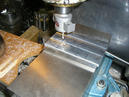
3. Set up block on Induma mill and center over first circle. Cut 1.375” circle through block.
(continued)
MANUFACTURE OF CUP HOLDER FOR PORTABLE MISSION CONTROL UNIT
MANUFACTURING PROCESS, CONTINUED
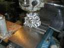
4. Stop to clear excessive ribbon of waste material. Retrieve another bandage and apply as needed per step 2.
(continued)
MANUFACTURE OF CUP HOLDER FOR PORTABLE MISSION CONTROL UNIT
MANUFACTURING PROCESS, CONTINUED
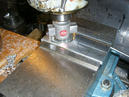
5. Center and cut opening 2 as in step 3.
(continued)
MANUFACTURE OF CUP HOLDER FOR PORTABLE MISSION CONTROL UNIT, CONTINUED
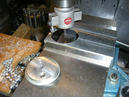
6. Deburr piece per Deburring Procedure, Document 0015.
7. Cut an oversized length of MS-0063-15 aluminum hinge.
8. Lay out three #28 holes on bottom leg of hinge and drill through.
9. Align holes on Cup Holder block and spot. Drill and tap three holes for #6-32 screws, #36 drill, .750” deep. Countersink with 82° bit.
10. Join hinge to block with three #6 SS oval head machine screws.
11. Align block to 1.00” distance from right edge of Top Work Surface. Drill three #28 holes through hinge and panel 3.
12. Attach cup holder with hinge to panel 3, using 1” SS button head machine screws, washers and locknuts.
13. After checking fit, remove unit and mill hinge to block length minus .063” on left and right sides. Leave pin to block length, and replace unit on panel 3, per step 12.
14. Finish per specification 005, and test unit with two cups of coffee, then two cups of Tang. Flip unit back and forth repeatedly. Try out different cups. Place 4 lb. calibrated test weight on unit, then check for stress cracks or bending.
(continued)
MANUFACTURE OF CUP HOLDER FOR PORTABLE MISSION CONTROL UNIT
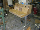
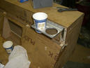
Mission Control Assembly during manufacture.
See Appendix in Procedures Document for Safety Notes
MANUFACTURE OF CUP HOLDER FOR PORTABLE MISSION CONTROL UNIT
DOCUMENT 00247
DATE: 29 OCTOBER, 2007
MANUFACTURING DIVISION, DEPARTMENT OF ROUGH SHAPES
BROOKLYN NAVY YARD FACILITY
Document Available in
Downloads section as bpl_cupholder.pdf
BPL home